Chapter2 – Network Layer (Part1)
Chapter2 – Network Layer
1. Introduction
In this chapter, we speek about OSI model, peer to peer communication principle and after that we focus on the network layer which is the third layer of the OSI model. For this purpose, we introduce IPV4 and it differents issues, such as the shortage of IP addresses. Many solutions have been proposed and discussed in this course.
2. OSI Model
the OSI model consists of seven layers. The top three layers are oriented application, while the lower four
layers are oriented communication and data transport. Figure 2.1 illustrates these seven layers.

Figure 2.1 – OSI Model.
Application Layer : Human computer interaction layer, where application can access the network services
Presentation Layer : Ensure that data is in a usuable format. Encryption and compression occur in this layer.
Session layer : maintains connections and is responsible for controlling ports and sessions
Transport layer : Transmits data using transmission protocols including TCP and UDP.
Network layer : Decides which physical path the data will take.
Data link layer : Defines the format of data on the network
Physical Layer : transmits raw bit stream over the physical medium (modulation, coding…).
3. Peer to peer communication
In order to allow an information transfer between two computers, each layer belonging to the OSI model of the source computer must communicate with its peer layer OSI model of the destination computer. This kind
of communication is called peer-to-peer communication.
The homologous layers thus exchange information called PDU (Protocol Data Unit). During a data transfer,
starting from the layer application to the physical layer, each layer places the PDUs received from the
upper layer in its own data field, PDU headers and trailers are then added to allow each layer to carry
out its functions.
This process is called encapsulation and is schematized in Figure 2.1.
For example, at the data link layer, the added header contains the physical source and destination addresses necessary for the execution of the layer 2 function.
At the receiving computer level, starting from the physical layer towards the application layer, each layer performs the reverse process by removing the header and possibly the tail added by its layer peer at the transmitter and sending the data part to the upper layer. This process is called de-encapsulation.
4. IPV4
A machine must be identified by a physical address (MAC) and a logical address (IP) to be able to carry out any data exchange. A machine connected to several networks must have as many network cards as network connections and therefore an IP address for each connection.
The IP address intervenes at the network layer of the OSI model. It is in the form of a 32-bit sequence, expressed for convenience as four decimal numbers separated by dots. It is composed of two parts: network part and host part. The first part identifies the network to which the machine is connected and the second part identifies the machine. The number of bits allocated to each of the two parts will allow us to know the class of the IP address used.
Several classes exist depending on the number of bits dedicated to the network part and the host part. Reserving a greater number of bits for the host part will make it possible to have a number of networks reduced in number but very large in size, the opposite is also true. The following table groups the different classes of IP addresses.
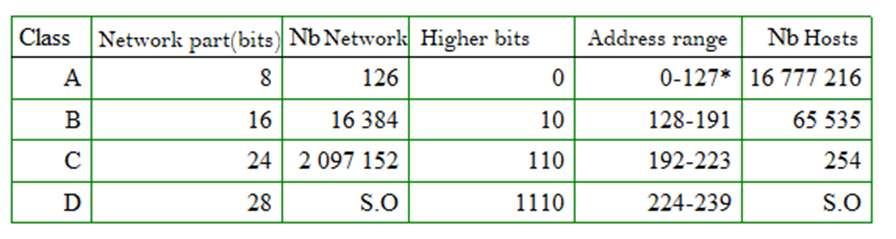
This table shows a poor distribution of address spaces. In fact, the difference in the number of hosts between the two first classes is very big. We don’t have an intermediate class between A and B.
Another problem is the shortage of IP addresses, which is mainly due to poor management of IP address allocations.
Several solutions have been proposed including: public and private IP addresses (NAT), subnetting CIDR (Classless InterDomain Routing), VLSM (Variable Length Subnet Mask) and IPV6 addressing.
5. Subnetting
To explain the principle of subnetting, we take a practical example.
Let take the Network ip address 192.168.1.0 whose network mask is by definition 255.255.255.0. Without subnetting, the number of possible hosts in this network is 254, which may be too large.
The proposed solution is to divide this address space into several smaller spaces. For this purpose, we reserve 3 left bits of the fourth byte, in this way, we increase the networks part by three bits and we decrease the host part by three bits.
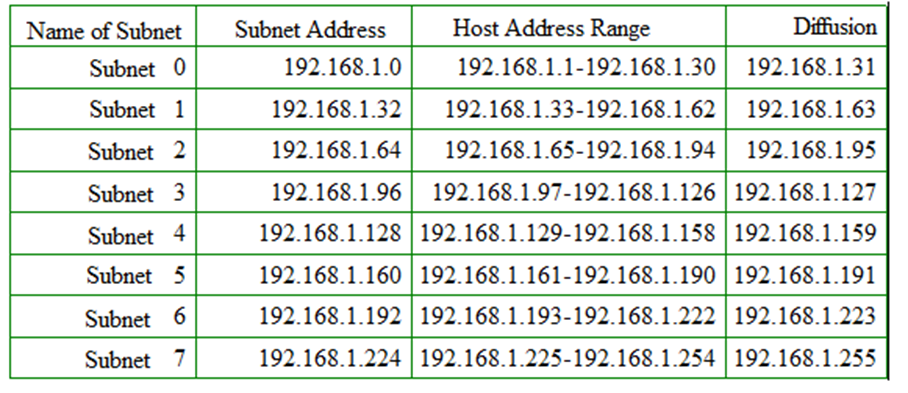
Subnet 0 and Subnet 7 should not be used if the routing protocol is classful and does not carry any network mask information, as is the case for RIPv1.
In fact, the address 192.168.1.0 can be considered as the network address for two different networks :
1- The one with the mask 255.255.255.0
2- The one with the mask 255.255.255.224
Also, 192.168.1.255 is the diffusion address of the two networks : 192.168.1.0 and 192.168.1.224.
The protocols RIPv2, OSPF, and BGP integrate the subnet mask, the exclusion of all-zero and
all-ones subnets is then unnecessary.