Chapter1 - Local Area Network (Part3)
5. Hardware or Network
device
Figure 1.4 – Network device (a) Repeater
(b) Hub (c) Bridge (d) Switch (e) Router
Ø
Repeater
-
It is a 2-port
device.
-
Operates at the
physical layer
-
Amplify and
regenerate the signal
-
The 5-4-3 rule is
designed for the number of repeaters and segments on shared access.
Ø
Hub
-
A Hub is a simple
type of repeater that operates at Layer 1
-
Multiport repeater,
-
Enable the
connection of multiple devices to the same network
-
Hub does NOT break
up collision domains
-
All ports on a
network hub sent the same traffic
-
It doesn’t make
decision about traffic
-
Can cause congestion
-
Gradually replaced
by switches and has not been
manufactured for a long time
-
3 kinds
o Active Hub
o Passive Hub
o Intelligent Hub
Ø
Bridge
-
Network bridge is
Layer two devices.
-
Had only two ports.
-
Filters traffic between two physical segments based on MAC
addresses.
-
Break up collision
domains and can reduce network congestion.
-
Separate the
network into two collision domains.
Ø
Switch
-
Switch is a Layer 2
device
-
Switches are the
basic building block of Ethernet networks
-
Forwards unicast traffic (to a single host)
-
Switch break
up collision domains and greatly reduce network congestion compared
to network hubs
§
learns the
MAC addresses of the connected devices
§
When traffic needs
to go to a specific device, the switch sees the MAC address in the packet and
sends it to only that device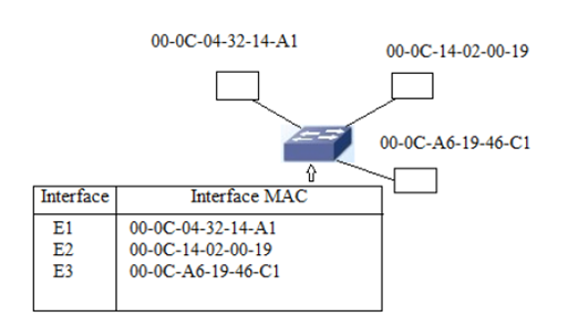
Figure
1.5- Commutation table
-
Forwards Broadcast (to all) and multicast (to some) traffic
through all ports except the original port
Ø
Router
-
Layer 3 devices
-
They are the
network device that deals with IP addresses
-
Route packets between networks (interconnects different IP
network domains)
-
Forwards IP traffic
using its routing table to the right destinations
-
Is characterized by a limited number of interfaces,
-
Has a great diversity of interfaces allowing this professional
equipment to connect to any technology
6. Example of LAN
Figure1.6 – Example of LAN
In the picture, we have a Hub, also known as multiport repeater.
This is the most basic device that allows central connecting. It connects each
of the computers (hosts) and servers by cables. When a host need to send data,
it first sends data to the Hub, where it is amplified and broadcasted to the
rest of the network. Broadcasting means that the data is sent out to every host
on the network. Only the real receiver keeps the data, the rest of the hosts
drop it. Despite the disadvantages, it was the standard for a long time.
Actually, switching technology is the standard and is more efficient.
7. Kinds of LANs
7.1 Client/Server LANs
A client/server LAN consists of
several devices (the clients) connected to a central server. The server manage
the storage of information, application access and network traffic. A client
can be any connected device that runs or access applications. The clients
connect to the server either with cables or through wireless connections.
One can imagine a company's
information system as consisting of one or more databases and some number of
employees who need to access them remotely. In this model, the data are stored
on powerful computers called servers. Often these are centrally housed and
maintained by a system
administrator. In contrast, the
employees have simpler machines, called clients, on their desks, with which
they access remote data.
The client and server machines are
connected by a network, as illustrated in figure
1.4.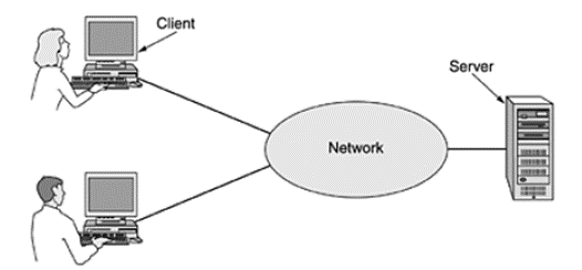
Figure
1.7 - A
network with two clients and one server This whole arrangement
is called the client-server model. It is widely used and forms the basis of
much network usage. It is applicable when the client and server are both in the
same building (e.g., belong to the same company), but also when they are far
apart. For example, when a person at home accesses a page on the World Wide
Web, the same model is employed, with the remote Web server being the server
and the user's personal computer being the client. Under most conditions, one
server can handle a large number of clients.
Two process are
involved in the client-server model as follow :
1- Client process send a message over the network to the server
process.
2- When the server process gets the request, it performs the
requested work and sends back a reply.
These messages are
shown in Figure 1.5.
Figure 1.8- Exchanged messages between client process
and server process.
The
folowing table regroup the advantages and disadvantages of the client/server
model.
Advantages
Disadvantages
Centralisation : informations are placed in a single location. Updating data and resources become easier.
Traffic congestion : if too many clients make request.
Security : data is well protected.
Robustness : if the server breaks down, the whole network will be disturbed.
Scalability : possibility of incrising the number of ressources such asclients and servers
Cost : the cost of setting up and maintaining the server is usually high.
Management : centralization help easier management
Maintenance : a specialized network manager should maintain the server
Accessibility : whatever the place or the platform, client or employees can access their informations.
7.2 Peer-to-peer LANs
Another type of model is person-to-person communication often named peer-to-peer communication. In this model, it is possible for one computer to play the role of client and the server at the same time. The simplest P2P network is a two directly connected computers (wired or wireless connexion). Both computers are able to exchange data with each other over the network. Both of them act either as client or a server depending on the situation.
Multiple PC scan also be connected by a large peer to peer network. As shown in figure 1.6, every person can communicate with one or more other people.
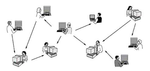
Figure1.9- In a peer-to-peer system there are no fixed clients and servers.
The following table shows the advantages and disadvantages of a peer to peer network.
Advantages
Disadvantages
Easy to set up
No centralized administration
Less complex
Not scalable
Less cost because the servers are not required
Not very secure
No need of administrator
Each computer can be client and server at the same time, which can reduce his performance significantly
8. Metropolitan Area Network (MAN)
A metropolitan network is a network, which covers a metropolitan area (city or suburb), and which allows at least two LAN networks to communicate with each other. This kind of network can be used in the case where, for example, several branches of a bank want to communicate with each other.
9. Wide Area Network (WAN)
WAN is the acronym of Wide Area Network. This kind of network ininterconnect several geographically dispersed local networks, access remote file servers and share resources (printers, computers and other equipment that can be connected to a LAN). In this way, possibly distant companies can communicate with each other, exchange information files, share resources...etc. Users of this network must be able to communicate and access remote resources in real time. The most common technologies for wide area networks are: ISDN, DSL, Frame Relay...
This network speed is less than the LAN network speed.
10. Protocols
Protocols mean set of rules. It is a formal description of message formats and the rules two or more machines has follow to exchange messages. The key elements of a protocol are syntax, semantics and timing.
· Syntax Syntax refers to the structure or format of the data, meaning the order in which they arepresented.
· Semantics Semantics refers to the meaning of each section of bits.
· Timing Timing refers to when data should be sent and how fast it can be sent.
11. Collision Domain and broadcast domain
Collision domain describe a set of computer equipment (computers, printers, servers, etc.) connected to central not intelligent equipment (Hub for example). All data sent by one of the hosts equipment will arrive at the central network equipment and then be sent to all other equipment without exception. A network where many collisions occur has a negative impact on the good functioning of this network. Segmentation consists of dividing the collision domain into smaller collision domains by adding intelligent equipment (such as switch or bridge)
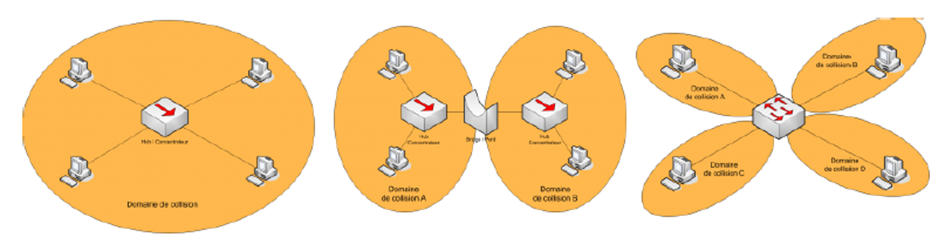
Figure1.10- Collision domain and broadcast domain.
To explain the broadcast domain, recall that a network entity can transmit data in unicast, multicast or broadcast. Suppose that we are in the case of a broadcast transmission, if the transmitted data crosses a Hub, a bridge or a switch, it will be broadcasted on all ports of these equipments. We know that the Hub is not able to process the received data and that the bridge or the switch will broadcast the data received if the destination address is a broadcast address (FF:FF:FF:FF:FF:FF).
The use of a router allows breaking the broadcast domain, since this equipment is not able to read physical addresses (MAC). It will not broadcast data therefore.
Reference
- Andrew S. Tanenbaum, and David J. Wetherall, Computer Networks, 5th Edition, China Machine Press, 2011
- CCNA1 courses.